Announcement

Collapse
No announcement yet.

Signal Stat Wiring

Collapse
X
 
  • Filter
  • Time
  • Show
Clear All
new posts

  • Signal Stat Wiring

    A question arose today about the wiring on the Signal Stat unit. I used Flying Tigers as my template http://www.flyingtigertransport.com/...t900wiring.jpg
    but have a question as this diagram conflicts with the WM300 manual.
    I have the Green and Red wires from the signal stat going to the L & R front parking light/turn signal as per the above diagram, but is the 2nd black wire from each lamp just going to ground or are they joined and then brought up to the headlight switch like the rear lights are?
    I used to have parking lights on the first indent on the headlight switch and they would go off as you pulled again to turn on the headlights. Now I have nothing. Headlight switch could be questionable too though....as could have been the poles that they were using on the switch.
    I am going back and rewiring the headlights as per the manual as they were done in a cadgy way to begin with, but would like to clarify the front parking/turn situation if I could.
  • #2
    Do your front turn signal lamps have two elements, IE a ground housing and two input prongs on the bottom? If so, then yes the extra wire is the parking lights. Just be sure you have the brighter element power wire on the blinkers and not the parking lights.
    I drive a DODGE, not a ram!

    Thanks,
    Will
    WAWII.com

    1946 WDX Power Wagon - "Missouri Mule"
    1953 M37 - "Frankenstein"
    1993 Jeep YJ - "Will Power"
    1984 Dodge Ramcharger - "2014 Ramcharger"
    2006 3500 DRW 4WD Mega Cab - "Power Wagon Hauler"

    Comment


    • #3
      The 1129 bulb and #81 bulbs are single pin 6 volt bulbs so you would need to change out the socket to a accept a dual element bulb to have both turn and park light up front.

      Comment


      • #4
        The lamps are two wire, two filament. By "input prongs" you mean the two contacts for the bulbs, or....?
        And if that's the case then DO run a common wire to the headlight switch?

        Comment


        • #5
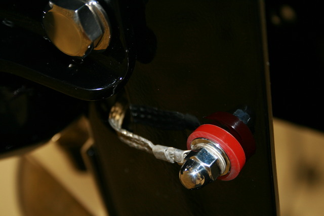
          Make sure your grounds are really grounding. Continuity test all studs and such to the frame ground or battery ground to check. Start simple and work from there. To save home run grounds you can weld a hidden stud near the light/switch/etc and have straps connecting everything. Engine/frame, frame/cab, cab/bed, etc. I TIG welded stainless studs when doing mine and had no issues.

          Comment


          • #6
            Thanks for the tips. All is in and working fine. One headlight was VERY dim initially, but cleaning the contact area for the bucket bolts corrected that.

            Only issue I am having now is with the Bosch American wipers (internal condition unknown as of now). I have the fused hot from Accessories on ignition switch running to the "OFF" side of the DS toggle. A jumper goes from there to the "OFF" side of the PS toggle. Both of the "ON" sides of each run to their own motors, and those motors are grounded. Is that it?

            Comment


            • #7
              AB Wipers

              That's correct. The body of the wipers are grounded. Having said that, I always separately ground all equipment back to a single ground "buss" point at the firewall. Check out my site www.flyingtigertransport.com look for the American Bosch Wiper link for more info.

              Hope this helps.

              Dave in Baltimore, Maryland USA
              http://www.flyingtransport.com

              Comment


              • #8
                Thanks for that, I followed the section on your website closely when wiring the signal stat, wipers etc.. All are functional now and I actually have a state inspection sticker!

                Comment


                • #9
                  Success!

                  I know the feeling of that accomplishment! Congratulations.

                  Comment

                  Working...
                  X