Announcement

Collapse
No announcement yet.

W200..

Collapse
X
 
  • Filter
  • Time
  • Show
Clear All
new posts

  • W200..


    I changed my fuel pump and filter this afternoon after watching the old one drip gas. While test driving it on the four lane, a guy pulled up beside me and motioned me to crank my window down. I obliged and he yelled 'Nice truck' at me and then asked if I was interested in selling it.
    I shook my head.
    We stopped for a red light. Truck idled fine, which it had quit doing before the replacement. He told me he's looking for a truck for his dad. Was I sure I wouldn't sell it?
    I nodded my head.
    Green light. It accelerated without hesitation. Going well.
    At the next red light, he asked me to give him a crazy number. Just throw it out there. Truck was still idling well, maybe even smoother than when I pulled out of my driveway. I told him I didn't think I'd take $10K for it.
    Looked like he thought about that a bit before he shook his head.
    The light turned green, I turned left and drove home. Slight hesitation as I pulled in my drive. Hmm.

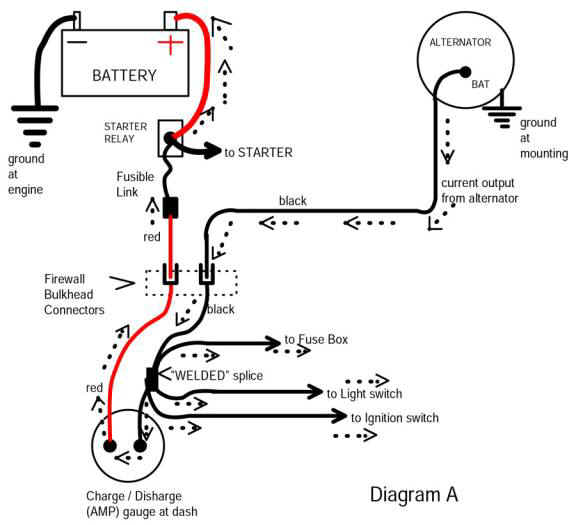
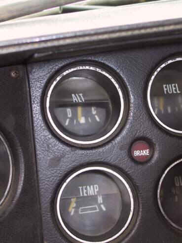
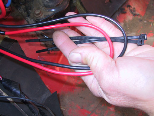
    All that's left are the electrical gremlins. I've already ordered some parts and and a book from Mark at Mad Electric out of California to bypass my truck's amp meter..

    I thought it was a nice compliment on my truck, considering it still sports the VFD's orange-peeled yellow paint job..

  • #2
    AMP gauges at the dash are troublesome.
    They should be by-passed, and then install a VOLT gauge.
    by Mark Hamilton
    THE PROBLEM
    The antiquated AMP gauge system has reduced more Dodge owners to pedestrian status than any other kind!
    And (wire) “terminal illness” at firewall connectors has also been a major problem.
    (Chrysler Corp. stayed with the old AMP gauge system long after other automakers switched to VOLT gauges, and Dodge trucks used the AMP gauge more recently than others, so we have used a Dodge truck as a model for this project.)
    Dodge is not the only make with concerns about AMP gauge systems, early FORD Broncos, International SCOUT, and many old cars and trucks used the AMP gauge system too. But when the electrical system will be up-graded with more powerful alternators and more accessories, the AMP gauge should be removed, and the “main power system” should be modified.
    With normal but frequent use, most of these Dodge trucks will have electrical wiring problems. The first to fail were often the trucks equipped with factory air conditioning. The air conditioning system adds a significant electrical load. And the “air” gets used in hot summer weather when heat will increase resistance at connections. The additional current flow when using the air conditioning and increased resistance with heat will break down the weak areas more quickly. With sufficient use, the non-air equipped trucks will also have electrical problems stemming from the same cause.
    Typical Dodge electrical problems result from a very antiquated power distribution system. The main source of power for the Dodge electrical system is based upon an old design AMP gauge at the dash and related wiring system. It’s a system that worked okay with a very small electrical system on Model A Fords way back in the late 1920’s. But the old AMP-gauge-at-the-dash system is not reliable with increased current loads of the more modern electrical system.
    Compounding the situation, the wiring system for the AMP gauge actually became weaker than it was over fifty years earlier. Assembly line labor was not so expensive in early years of the car. Affordable labor could consistently connect wires with “ring terminals” at screws or studs with nuts–resulting with reliable (low resistance) connections. With increased labor cost mandating fast moving assembly lines, and many more wiring circuits to install, “click together” connections have been widely used since back in the 1950’s. And by the 1960’s, even the AMP gauge (heavy current load circuit) was routed through a “click together” connection. The least reliable of “click together” connections for a heavy current load circuit is the male/female flat blade terminal design. And it happens that Dodge was built with this terminal design, even at the main power delivery circuit.
    In summary, the AMP gauge and related wiring found in Dodge trucks of the sixties and seventies period was built with a recipe for failure. A 70amp alternator supporting powerful electrical accessories was typical equipment by 1979, and the load was too much for the method of wiring construction used. Naturally, it’s a system that often reduced Dodge owners to pedestrian status.
    This feature clearly explains the shortcomings of using the old, traditional, AMP gauge at the dash. And largely because of the circuit design shortcomings, the best choice of gauge to monitor the electrical system is a “VOLT” rather than AMP gauge. A good explanation of the AMP vs. VOLT gauge may be found at www.autometer.com in the Tech Tips / FAQ section of the web sight. THE HISTORY

    In some ways, the Chrysler Corporation was pretty far advanced where electrical systems were concerned. (Chrysler gave us the Dodge, Plymouth and Chrysler line, and nowadays they all may be referred to as MOPAR.) Back in the early ‘60’s, MOPAR was the first to give us alternators rather than the older technology generators–Indeed the improvement was great. GM followed, and then Ford finally installed alternators as “standard equipment” on ’65 models.
    1964 year model Chrysler products showed up with “Fusible Link wires” for reliable short-circuit protection of the main power circuit from the battery to the electrical system. Chevy didn’t use Fusible Link wires until ’66 models.
    And Ford didn’t use Fusible Links until some years after GM.
    Chrysler/Dodge/Plymouth introduced a very good electronic ignition system with 1971 models. Ford introduced a somewhat less reliable electronic ignition with only some of their ’74 models. And GM gave us a very good electronic ignition with ’75 models.
    In spite of being the first to give us “break through” technology with components, it seems that the “DODGE BOYS” were reluctant to depart from a very antiquated wiring system. The old, traditional, “full current load type” AMP-GAUGE-AT-THE-DASH and related wiring system was still in use with ’79 Dodge trucks. The AMP gauge circuit wiring had to deliver electrical current used by the entire electrical system, plus handle current to recharge the battery. The problem was that current load and the alternator output rating was a large amount by the end of the ‘70’s. Alternators with about a seventy amp available output were standard with air-conditioned models. And a weak terminal design was used where the AMP gauge wiring passed through the firewall. The large demand for electrical current often resulted with failures in the lengthy AMP gauge circuit, even in vehicles that were relatively new.

    The original AMP gauge system served as the main power distribution system. This circuit is the power source for the entire electrical system. (see diagram A)
    Amp gauges at the dash were standard equipment with Model A Fords, back in the late 1920’s. And the fifteen amp capacity gauge at the dash worked fine with minimal electrical systems of that period. Current output from the small Model A generators was not even sufficient to support sealed beam headlights. (The old Model A was equipped with a small light bulb backed up by a large reflector in the headlight assembly.) The Model A only had one tail/brake light at the rear, a simple ignition system and a small battery about completed the electrical system. Such a small amount of electrical current flow through good connections at the AMP gauge wiring was no problem with the Model A Ford. And with current output limited by a cutout relay on the generator, the AMP gauge could handle the small battery charge rate. But as electrical systems became more powerful, Ford discontinued the old AMP gauge system long before the ‘70’s.
    GM also up-graded their system long before the Dodge Boys. When GM introduced the alternator with ’63 models, it was controlled by a more complicated but more efficient voltage regulator system. And the new GM system could support a warning light at the dash. The warning light was often standard equipment and the gauge was an option. GM vehicles built with the gauge option also had a more modern design of AMP gauge at the dash. The newer AMP gauge was a remote shunt type design–a length of the battery charging wire in the under-hood harness served as the shunt. The dash gauge and related wiring no longer handled heavy current load. Same with Ford in ’65 and newer model cars–the Ford system could work with a warning light at the dash, and cars that came dash gauges had a remote shunt type amp gauge.

    The Dodge alternator/voltage regulator system had no provision to operate a warning light. And Dodge (trucks) stuck with the old antiquated “full load type” AMP gauge design, at least into the late 1980 models. As is typical of Dodge trucks that were used a lot, the AMP gauge in this ’76 Dodge was burned out. The plastic mounting area behind the dash is completely melted, and the lens and plastic trim is shriveled too. (This gauge is included in Diagram A.)
    Amperage is a measure of current flow, and all of the current used to recharge the battery was routed through this gauge–which caused the gauge to display the battery charge rate. Both the alternator and the battery were mounted up front, under the hood. And the AMP gauge was at the dash. It was an arrangement resulting with a very long wire circuit charging the battery.
    Large amounts of current flow through the AMP gauge will generate some heat too. The plastic cover at this gauge was only distorted by heat–but some Dodges have sizable holes burned in the dash where the AMP gauge used to be. Apparently, the shunt in the gauge has a sufficient amount of resistance to generate a damaging amount of heat with battery charging current flow.

    A previous owner had replaced the terminals at the back of the AMP gauge, and then did a weak by-pass of the gauge by taping the two wire terminals together. (No doubt an attempt to get the old Dodge up and running.) It’s fairly common to find the wires disconnected from the gauge, and a machine screw and nut clamping the terminals together, and finished by wrapping the screw and terminals with tape.

    The AMP gauge wiring passed through the “firewall bulkhead connector,” where standard, .250 inch wide, male/female flat blade connectors were used. (This connection is shown in Diagram A.) These terminals were reliable with circuits of much less current flow, as with turn signal, clearance lights, and temp or fuel gauges. But the design was certainly not up to the job of handling the entire alternator output. This was a problem spot in the AMP gauge system that often made Dodge owners walk.

    Arrow A in the photo at the left points out a melted cavity in the plastic connector body, where a case of “terminal meltdown” occurred. This connection served as a pass-through for the main wire from the alternator to the dash area. When driving, the entire electrical system current load will pass through this connector. (Also seen in Diagram A.) Ignition, lighting, heater fan, accessories, and electrical power in general flows through the connector. The wire color code is black at this circuit, and this model was equipped with 10 gauge wire. (Many earlier models had only a 12 gauge black wire.)
    Arrow B points out the red, 10 gauge, battery charging wire.

    After removing the connector with the red 10 gauge battery charging wire, a close inspection revealed that this side of the AMP gauge circuit was also suffering from a case of “terminal illness.” (See arrow in photo at the left. This is the terminal used by the 10 gauge red wire at arrow “B,” above.))
    The plastic connector body surrounding the female flat blade terminal is beginning to melt away. And severe oxidation of the terminal itself is evidence that this terminal has been glowing hot. Notice that the other terminals in the connector body are still in good condition. The rusty appearance of this terminal is typical of wire terminals that have been hot while handling large amounts of current flow. (If moisture had caused the oxidation, all the terminals would have been corroded.)

    We have opened part of the dash wire harness, to show the factory “welded splice” where wires branch off to the ignition switch, light switch, and the fuse box. (This splice is shown in Diagram A.) The “welded splice” is insulated by a factory installed, sticky cloth tape.

    The original tape has been removed for this photo to expose the “welded spice.”
    Pressure and heat fused the copper wire strands together when making the splice. The method seems to be reliable, as in thirty years of workshop experience the author has never seen a failure with this splice. When electrical power loss occurs, this is certainly not the first place to look for the problem.

    Comment


    • #3
      Part Two – AMP gauge WIRING FIXES (Dodge was used for this work shop model)

      By Mark Hamilton
      We have seen the weak areas, now we will make improvements. The male/female flat blade terminals for the AMP gauge wires at the firewall connector will be eliminated–because they are the weakest link in the system. The AMP gauge will be disconnected and by-passed–because the gauge often fails and sometimes it burns dashes. Alternator output will be routed directly to the BAT. POS. stud at the starter relay–because it’s the most direct routing of power. And, we will make use of both legs of the old AMP gauge circuit–because it doubles the strength of the main power-up circuit to the “welded splice,” which serves as power distribution.


      When everything is working properly, the alternator is the source of power to the entire electrical system. With this new system, we have alternator output delivered to the BATTERY POSITIVE stud at the starter relay. The stud at the starter relay now becomes the “main buss” for power distribution. Battery charging current will flow directly to the battery, via the positive battery cable. The “welded splice” in the dash wire harness still serves as a junction for power distribution–but now we are sending power to the “welded splice” through both of the existing wires that were part of the old AMP gauge system. And the AMP gauge is by-passed.
      The system mostly uses existing wires that were already in the wire harness. But since we are disconnecting, bypassing, and ignoring the AMP gauge, we can rearrange the wires to form a much stronger system. The male/female terminals at the firewall connector are also by-passed, the wires now pass directly through connector body connection.
      We have also used the proper Fusible Link wires for short circuit protection. A 14 gauge Fusible link is protecting the 10 black wire circuit to the alternator. And a 16 gauge Fusible link protects the power-up wires to the “welded splice,” which serves as main power distribution to the dash area.
      Craftsmanship and wire splicing methods will be critically important to reliability with the new system. We are working on wiring that must handle large amounts of electrical power every time the truck is driven. Our work has to be good or the outcome will be no better than the weak factory system. We have to use a few splices to complete the up-grade, and splicing is a job that not everyone does well. Resistance at all spices and connections must be minimized. Crimp-on butt connectors with yellow plastic insulation, wire nuts, or twisting and tapping wire together will not be reliable splicing methods. The old method of crimp first, then solder, then insulate is still the most reliable.
      The best parts for the job are non-insulated butt connectors, which are made of copper and are tinned with solder. Good quality shrinkable tubing will insulate the splice, and a length of it must be slipped down the wire before installing the butt connector. We will also need a soldering gun or soldering iron, and a lead/tin rosin core solder.

      After stripping the ends of the wires, we slipped shrinkable tubing down the wire. Then we crimped the non-insulated butt connector onto the wires. And then soldered the connection.

      Electrical tape may be used for the first layer of insulation, before slipping the shrinkable tubing into place. (We are using this option because it provides a little extra padding and insulation over the splice.)

      Then slide the shrinkable tubing into place, and apply heat to shrink the tubing tightly for a good seal. A disposable lighter works well when there is no breeze. A heat gun works very well and is safer too, as it is flameless. Hair driers do not produce enough heat to activate the better shrinkable tubing. (The splice shown in the photos above is where we have disconnected and by-passed the AMP gauge at the dash.)

      Using a drill slightly larger than the O.D. of a 10 gauge wire, we are drilling out one of the slots in the engine side of the firewall connector body. A new wire will pass directly through the connector body without the weak male/female terminal arrangement.
      Both sides of the bulkhead connector must be drilled–the engine side and the dash wire harness side.

      In the photo above, we are drilling out the dash harness side of the bulkhead connector. Before drilling this side, check from under the dash to be sure that wires are clear at the backside. And drill just deep enough to go through the connector–there are many wires at the other side, which could be damaged by the drill.
      This connector body is easily dismounted from the firewall by releasing the latches. Removing the connector body and then dragging it under the dash will allow drilling it from the other side. With either method, be sure to get the correct slot so that the holes in both of the connector bodies will be aligned after assembly.
      Often the old terminal is melted into the plastic connector body and tightly embedded. If the terminal cannot be removed without breaking the connector body, then we can use available unused slots for the new direct pass-through.

      We have cut the original 10 gauge black wire from the alternator to the connector, and then removed the terminal with wire remnant from the connector body. (see arrow A)
      Splicing on a new length of wire has lengthened the original alternator output wire. Now it is routed to the starter relay, where a fusible link will be installed. (Arrow B points to the splice.)
      At the dash side of the firewall connector, we also cut the wire and removed the terminal from the connector body. And we lengthened the wire at the dash side–it now passes directly through the drilled out connector bodies. (see arrow C)

      At the dash side of the firewall connector, we have cut and lengthened the red and black 10 gauge wires. Both have been left long enough to pass through the holes drilled in the connector body and reach out to the starter relay area. Plus we added an extra 12 to 15 inches in length, which will be bundled to the dash harness.

      The extra length bundled at the dash side of the wires will provide opportunity for service work. Should we ever need to inspect, test, or clean other terminals at the connectors, we can always remove the nylon ties and drag the extra length of wire through the connector bodies. Then the engine side connector body may be unlatched and slipped over the 10 gauge wire for access to terminals in the connector.

      The photo at left shows the fusible Link installations, where the new wires will connect to the battery positive stud at the starter relay.
      The red and black 10 gauge wires connect to a 16 gauge fusible link wire, which is actually identified as a metric size on this particular fusible link. (1.0 sq mm is the metric equivalent of 16 American Wire Gauge size.) This circuit powers up the welded splice in the dash harness, which powers up all switches, fuses, and circuits at the entire dash area.
      Short-circuit protection for the black 10 gauge wire to the alternator is provided by a 14 gauge fusible link (the light colored of the two, which is actually a 2.0 sq mm metric equivalent.)
      The up-grade really is quite simple, and it does provide remarkable improvements to reliability and electrical system performance. The Dodge alternator/voltage regulator system will perform well with the up-grade. Expect more consistent voltage throughout the system as resistance is significantly reduced at the main power wiring.

      Craftsmanship will have to be good, for the new system to be reliable. We are working with the main power delivery to the entire electrical system. Current to operate the entire system will flow from the alternator, through this circuit, every time the vehicle is driven.
      Crimp-on connectors will not be good enough! They are prone to “Thermal Run-away” problems, which is exactly what happened to the crimped on butt connector shown in the above photo.
      M.A.D. offers very quality non-insulated terminals made of “tinned” (solder coated) copper, which are perfect for the crimp first, then solder, then insulate with shrinkable tubing connections. (As with the splice that shown in this feature.)
      The “tech is made simple” book, also available in through the M.A.D. catalog, teaches splicing and soldering techniques, all about the “Thermal Runaway” problem, and all about Fusible Link wires.
      And the M.A.D. catalog offers excellent wire strippers and terminal crimping tool, ideally suited for this kind of work.

      Comment


      • #4
        That is a fantastic story Chewie, your W200 was absolutely showing off for the guy, our Power Wagons have such a personality of their own.

        The ammeter article was a great read as well thank you.
        1967 W200.aka.Hank
        1946 WDX.aka.Shorty
        2012 Ram 2500 PowerWagon.aka Ollie

        Life is easier in a lower gear.

        Comment


        • #5
          So today I did the basic amp gage bypass by double-nutting the factory ring terminals on a macine screw. The truck runs much better. No hesitation and uninterrupted idle. I left the finish bezel off the dash so I can still reach the 'splice' to check for any heat build-up until I can get to the rest of the bypass.

          Mark's kit came in the mail on Friday. The booklets are well written and easy to follow. I am also going to put a relay on the headlight circuit to brighten those up.

          Comment


          • #6
            BRIGHTER HEAD LIGHTS

            Getting out of the DARK AGES!
            It takes more than a powerful alternator, and more than changing to powerful replacement headlights, to get brighter headlights on these older cars and trucks.

            The above photo was taken with High Beams ON, and the engine was running at highway cruise RPM. 14.1 volts measured at the Horn Relay was perfect. (It’s the main power distribution buss-bar in this electrical system.) But the headlights were only running at 11.5 volts!
            The voltage drop to the headlights in the above measurements was typical, as the headlight system on many cars is under-wired
            The headlights on our older cars and trucks are not very bright. They weren't when these cars were new. But when those cars were new, we didn't have anything better to compare our lights to. So the dim headlights were accepted as normal. Nowadays, many people replace the old headlight sealed beams with more modern HALOGEN replacements. It's true that the halogen's do not look yellow at low voltage, like the old sealed beams did. But the HALOGEN replacements also do not produce maximum illumination when operating at low voltage.
            Thinking of popping in killer European H-4 headlights? Unless the "real problem" is fixed, those powerful replacements will only compound the built-in deficiency. That's true because they will draw more current, resulting with even greater voltage drop in the "under-wired" factory system.
            Furthermore, Our American made cars and trucks have had automatic-reset circuit breakers built into the headlight switch for many years. And the circuit breaker is not rated for the greater current draw of those powerful H-4's.
            Many owners of Ford cars and trucks, built in the '60's and '70's, especially with the four headlight systems, are familiar with the headlights flashing OFF and ON. (Like erratic Morse Code, after driving awhile on High Beams.) The problem occurred because the circuit breaker in the headlight switch was weak. Simply installing H-4's in most of our older cars and trucks will result with the same effect known to old Fords. (The circuit breakers in original factory headlight switches cannot handle the extra current draw of the more powerful headlights.)
            HOW BAD IS THE EXISTING PERFORMANCE?
            Lighting systems engineering data has it that if we drop the voltage delivered to a light by 10%, then illumination out-put is reduced by over 30%. Going from 14.0 volts down to 11.5 volts is a loss of nearly 18%! As we shall see in photos–No wonder those old cars and trucks have dim lights (when factory equipped). The goal with electrical systems is to keep voltage drops within a 2% loss.
            If you're wondering how much the up-grade would help your favorite car or truck, it's really quite simple to do as we did and take measurements with a VOLTMETER. (The photo captions explain the voltage measurements recorded by these photos.)
            If voltage measured at the back of the headlight, with High Beams ON, and engine running at highway cruise RPM, is less than 13.5 volts–Then this headlight/relay up-grade will be an improvement. Most factory built cars and trucks will not perform better than 12.0v - 12.8v range, and many will drop below 12.0v, even with perfect factory wiring.
            TIP: The meter wires must be connected to the head light terminals with the car's wire harness connected to the headlight. Even with "two headlight" systems, the High Beams are higher in wattage (they draw more current), and so the system should be tested with High Beams ON.
            In photos and captions, here are the before and after the test voltage measurements at key parts of the electrical system.

            High Beams ON, Engine running at highway cruise RPM. (Photo taken indoors, evening, the hood was blocking overhead shop lights–so the powerful camera flash "strobe" froze the alternator fan as if it was still.) The Alternator system is working perfectly–that's definitely not the problem.
            This car was previously up-graded to a GM DELCO, 63amp, model 10SI, built-in voltage regulator system. It is properly wired using M.A.D.'s part # ALT-1, Alternator Wiring Kit. The kit's new 8 gauge wire is routed from the alternator directly to the horn relay buss-bar.

            High Beams ON, plus heater fan ON medium speed, plus windshield wipers ON, Engine running at highway cruise RPM–barely over 11 volts at the dash!
            WE HAVE A PROBLEM HERE!
            The more switches we turn ON, the lower the voltmeter shows. The dash-mounted voltmeter gives us the indication that the alternator is not able to keep up with system demands.
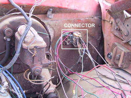
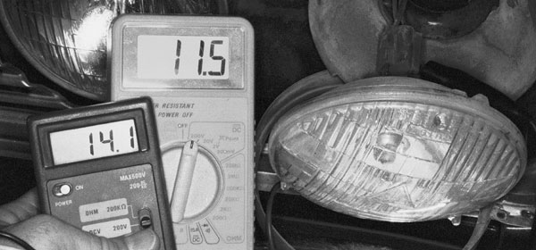
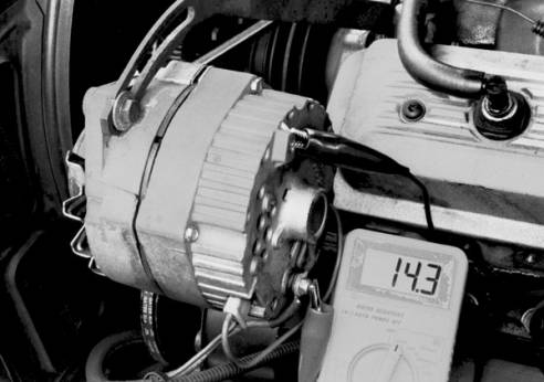
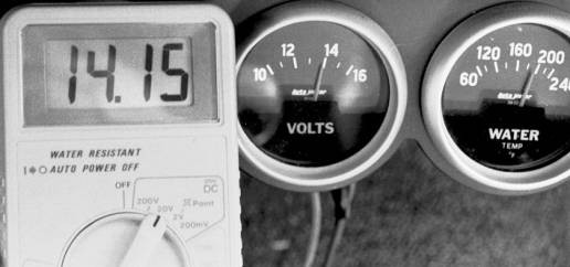
            But, we went back to the alternator, and to the battery, and to the horn relay buss-bar, (the "key check-points") and rechecked voltage levels. With the engine running at highway cruise RPM, lights, heater, and wipers ON, we had 14.1 to 14.3 volts at all the "key check-points" under the hood. (Which is perfect.)

            Sometimes in attempt to learn, "Just who is telling the truth here?"–It's a good idea to get second and third opinions. Ha! It turns out that all three voltmeters gave us pretty close to the same story.
            We got out another digital voltmeter, and connected two digital voltmeters to the stud terminals at the back of our dash mounted voltmeter, and ran the engine at highway cruise RPM, no lights or accessories ON.
            The digital meter on the left is actually the most accurate of these three. It was by far the most expensive. A reputable company, which calibrates and certifies diagnostic equipment, has checked it. And its readings are always consistent with other "high-end," expensive meters. Also, when switched to 20v, it measures to the nearest 1/100th of a volt.
            And, after this photo was taken, we did switch the lights ON, and the heater to medium, and found that all three voltmeters dropped back down to less than 12 volts. But yet, under the hood still showing 14 volts.
            Well now, what we have going on here is "voltage drop," in the factory wiring, to the dash area. The wiring in the car was inspected, and found to be in perfect condition–the problem is with design, not with defective parts or wiring!

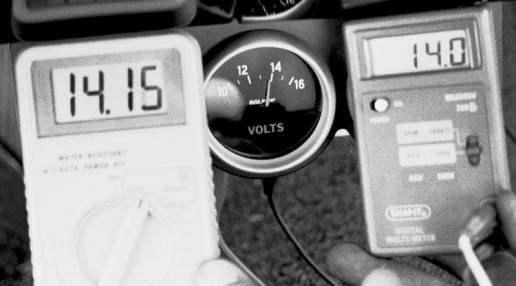
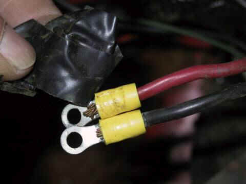
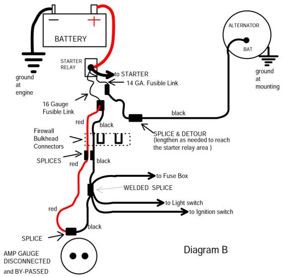
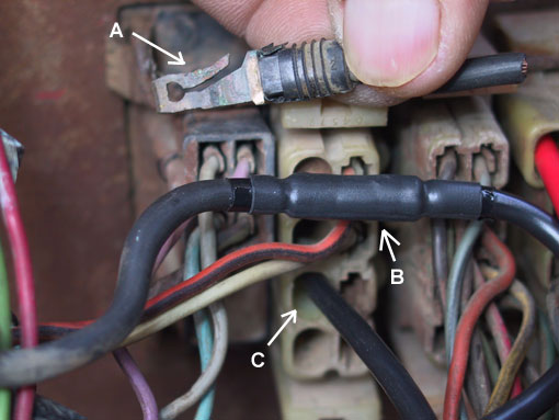
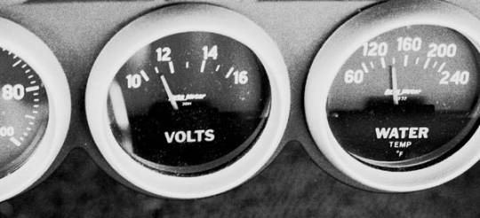
            We even looked at the factory wiring diagrams, and found that the "battery live" buss-bar behind the fuse box was directly connected to the dash area "main feed wire."
            So, we could read voltage at the dash area main feed wire, from the fuse box, and we did. High Beams ON, heater fan on medium, engine running at highway cruise RPM. We measured only 11.22 here, (still with over 14 volts under the hood). Yep! We definitely have voltage drop in the dash main power-up circuit. And the same wire powers-up the headlight switch!

            The term "buss-bar" means a "common" connection, where wires all connected to the same circuit can come and go.
            "Junction block" is another term often used to describe this function.
            On our project car, the alternator output wire is routed directly to this buss-bar. The dash area main power-up wire originates at this buss-bar. The battery charging wire is connected at this buss-bar. And, the voltage regulator takes "sensing voltage" reading here, and adjusts alternator output to maintain voltage level at this buss-bar (14.0v to 14.5v).

            Comment


            • #7
              Part 2 BRIGHTER HEADLIGHTS And now, a test of performance
              after adding RELAYS for the Head Lights


              Relays can be used as "remote control switches." It takes only a tiny amount of current to turn the relay ON. But when switched ON, the relay delivers power directly to the accessory. ("high gain" operation)
              We can install headlight relays next to the main power distribution buss-bar at the horn relay (where the old voltage regulator was).
              The factory "front lighting system" wire harness is routed just above that area, in route to the headlights. We can cut and detour the factory High Beam wire and Low Beam wire to the relays, and now the factory system will only have to switch the relays ON, instead of directly powering-up those big headlights.
              The headlights are up front, and the alternator is the source of electrical power; and the alternator is mounted at the front of the engine. It’s logical and sensible to mount RELAYS up front. Use existing wiring to switch the RELAYS ON, and then the relays will send full power to the lights. (And use of the relays takes headlight current load away from the dash wire harness, and so the ignition and entire electrical system will benefit too.)

              This test was done after the relay up-grade, with High Beams ON, engine at idle RPM. 14.0 volts measured at the horn relay buss-bar. 13.96 volts measured at the back of the headlight. (Before the relays, we had only 11.5 volts at the headlight, with 14.1 at the Horn Relay, at highway cruise RPM.)

              This test was done after the relay up-grade, with High Beams ON, engine at highway cruise RPM. (And it's a good thing our testing is finished, because the engine is warming up with so much "running in place.")
              With the current load to support the headlights removed from the dash wiring and switches, we took away the voltage drop in the wiring to the dash area.
              Now the dash mounted voltmeter will no longer "lie" to us when we switch the headlights ON. The ignition will not become weak. The dash lights will be brighter. And other accessories will be more powerful too.
              The first time the car was driven at night, the improvement in the headlights was remarkable! Now the lights are very bright.
              Everyone who has used our relay kits for the headlight system agrees that this is absolutely the best-for-the-money electrical up-grade. It adds reliability too, by removing current load from weak factory connections and switches. Considering the years of hassle free service, enjoyment, and safety, this is without a doubt the most sensible up-grade possible. It beats out expensive and often over-promoted luxuries like big sound systems, racing ignition systems, "high-end batteries," chrome alternators, and gadgets.
              Overall, the headlight relay up-grade makes these old cars and trucks more useful and enjoyable to drive.
              Two of our part # RLY-1 Relay Kits are required for the headlight system up-grade–ONE for LOW BEAMS, and ONE for HIGH BEAMS. (Even with "two headlight system" cars.)
              And for people who would like to learn more about electricity, voltage drop, assembly craftsmanship, Fusible Link wires, and more, we offer the "tech is made simple" book. The book is easy reading, and it's filled with great photos of craftsmanship and wiring techniques. Fundamentals of electricity are explained through cartoon-like illustrations. INSIDE OF THE HEADLIGHT SWITCH


              (The switch shown in the photo was removed from a FORD car. We ground off the rivet heads, punched out the rivets, and pried the cover from the switch, for a look inside.)
              Call-out labels with arrows point to various parts of the two circuit breakers in a typical headlight switch, shown in the photo above.
              A = Battery live "buss-bar," which also serves as mounting for the stationary contact points of the circuit breaker.
              B & C = Circuit breaker contact points.
              D & E = Resistance calibration notches in the movable arm part of the circuit breaker.
              F & G = Movable arm, metal strip, part of the circuit breaker.

              Comment

              Working...
              X