Announcement

Collapse
No announcement yet.

Alex's '42 WC53 Carryall Build Details - Cummins ISB170

Collapse
X
 
  • Filter
  • Time
  • Show
Clear All
new posts

  • Alxj64
    replied
    Also, some transmission stuff happening. Working out the linkage positions for the shifter. I am having to leave just a touch of "slop" ever so fine amount, in the linkage joint to allow for the differential in shift positions. In certain gear positions, the shifter handle is either high or low in the detent but will still interlock. This slight bit of slop is something I want to bush out with a grommet or something servicable rather than at the moment the hole for the rod end is a touch oversize and the nut is left loose.

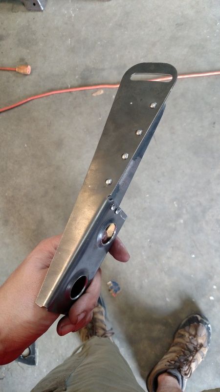
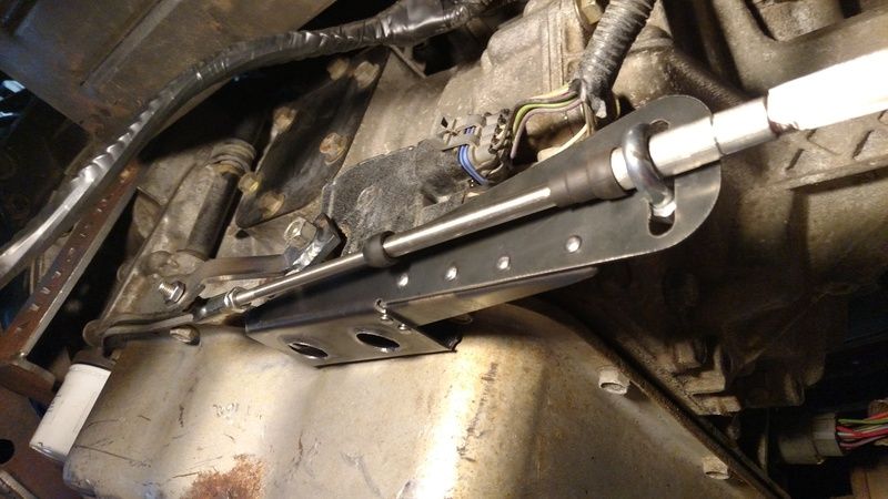
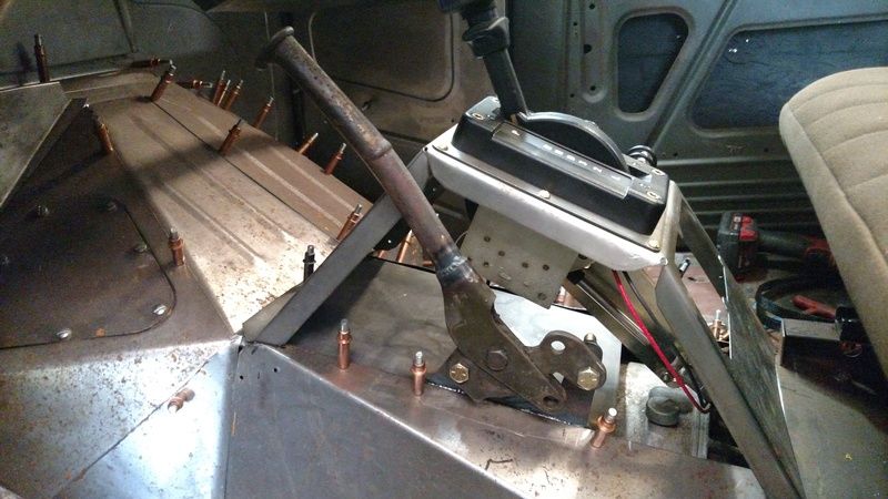
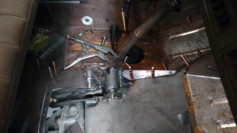
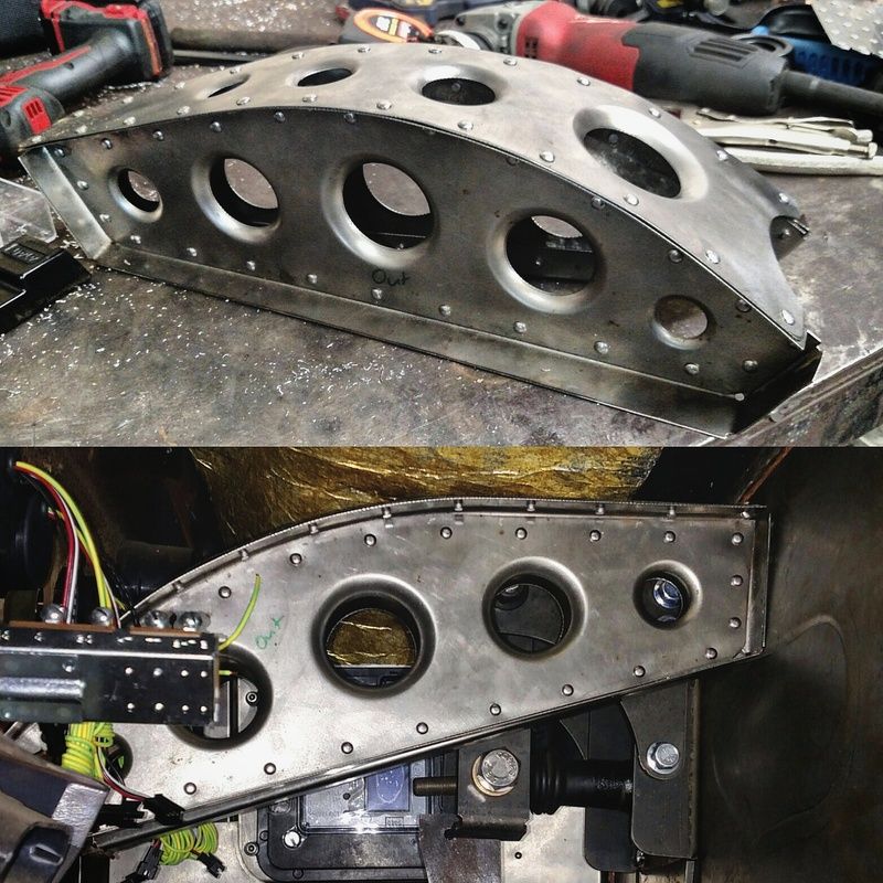
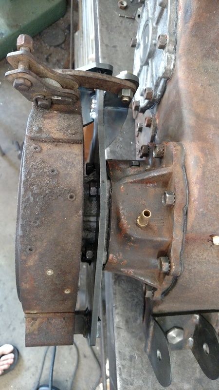
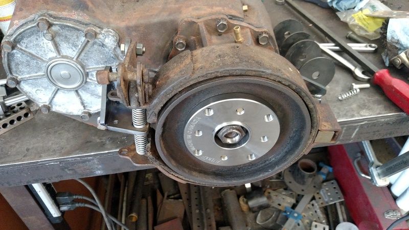
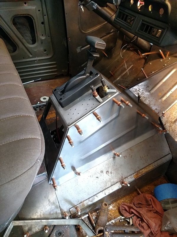
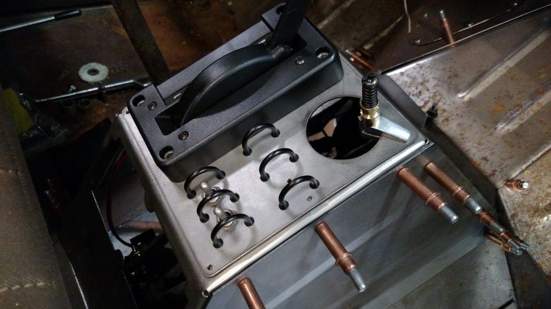
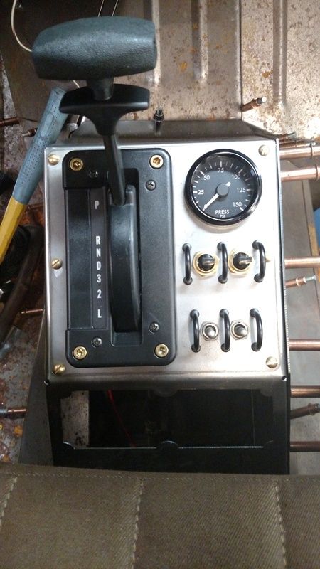
    I had to make a bracket that put the lever, of a calculated radius, in the specific location, with the cable mount in a specific location, with the cable traveling through the tangent of the arc and stopping at the correct location. I gave myself some fine adjustment on the cable position.


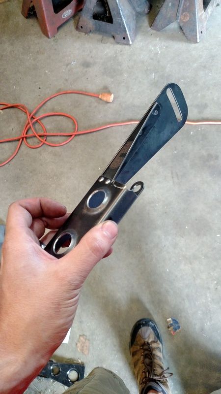
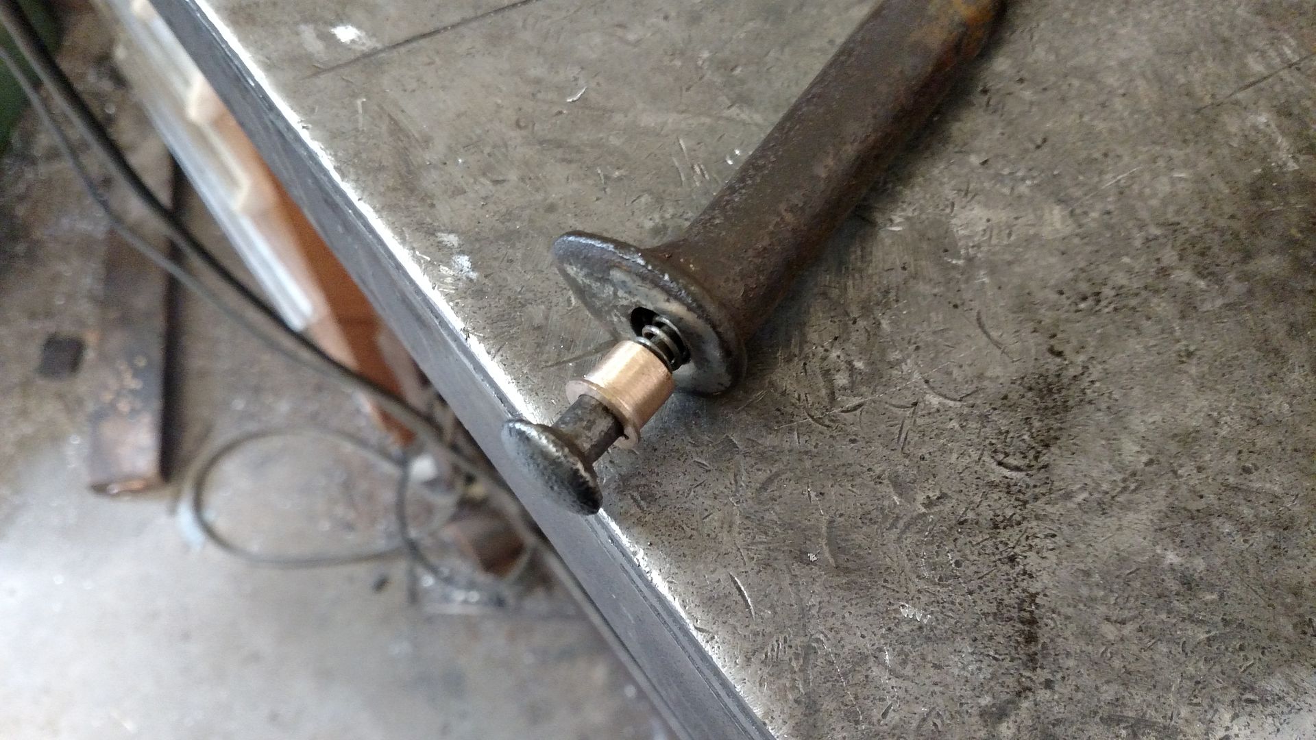
    I added the riveted in gusset after realizing that the shifter required a little more force than I originally anticipated as I was using a shorter lever than stock.

    Leave a comment:


  • Alxj64
    replied
    Working on the E-brake handle and transmission shifter stuff.

    New Bushing for E-brake push button on a stock handle I shortened.


    Shortened handle and hard mount to operate a push pull cable.


    What a mess.. but the mechanics of it work great and the handle is a nice spot.

    Leave a comment:


  • Alxj64
    replied
    Originally posted by Iowanogre View Post
    Impressive, I truly appreciate watching this build come together. I am looking forward to seeing it in person.
    Thank you for sharing with us.
    Thanks for the positive words. Its certainly a passion of mine now for sure. This truck is no doubt my mistress in life.

    Got the dash brace built. The previous owner had removed it because of his handling pedal and master cylinder setup. I could shake the dash by hand sitting in the truck, so that had to be fixed. This should do the trick. 20 Ga sheet with 1/8" solid driven rivets.

    Leave a comment:


  • Matthew Welcher PWA
    replied
    Impressive, I truly appreciate watching this build come together. I am looking forward to seeing it in person.
    Thank you for sharing with us.

    Leave a comment:


  • Alxj64
    replied
    Twin "switched" air-shift ram setup for the divorced NP205. It is still getting a top spreader plate brace that will also hold the bulkhead end of the parking brake push/pull cable as you can see the drum lever is a nice straight shot back from this.... yes that was on purpose. I still need to order fittings and lines but figured I'd do all that once I know how many 90s etc, that I need.


    Leave a comment:


  • Alxj64
    replied
    Originally posted by Desoto61 View Post
    Not sure about yours, but supposedly some of the later setups had another spring on the bottom of the activation rod, thinking I may try and add this to mine as it should help with activating the brake, as it is now it can be really tough to get the lever to the next tooth on the ratchet mechanism since there is not much give to the mechanism as set up. Not that I use it a lot, it's flat around here so I just usually leave it in gear, but part of that is how tricky it can be to get the parking brake on and off.

    I do need to figure out some sort of switch so I can wire up an e-brake light, probably easier on the lever than the brake itself.

    Awesome work otherwise, amazing how much cool stuff you can do with the right toys!
    Yes, I was going to spec' out a stiffer short spring to add in there as that "sweet spot" finder for tightening the band correctly. I don't have it and VPW didn't have it listed in their catalog when I ordered these.

    Thanks for the compliments! I am at the end of toys though, as I am out of space. The bridgeport really was the deal closer on the ability to come up with very specific items. My lathe needs a bump up in size. You can do small work on a big lathe but you can't do big work on a small lathe.

    Leave a comment:


  • Desoto61
    replied
    Not sure about yours, but supposedly some of the later setups had another spring on the bottom of the activation rod, thinking I may try and add this to mine as it should help with activating the brake, as it is now it can be really tough to get the lever to the next tooth on the ratchet mechanism since there is not much give to the mechanism as set up. Not that I use it a lot, it's flat around here so I just usually leave it in gear, but part of that is how tricky it can be to get the parking brake on and off.

    I do need to figure out some sort of switch so I can wire up an e-brake light, probably easier on the lever than the brake itself.

    Awesome work otherwise, amazing how much cool stuff you can do with the right toys!

    Leave a comment:


  • Alxj64
    replied
    Parking brake bracket is nearly done. Clocked it to where the pull rod has good clearance. I machined the spring pin hole in the square stock yesterday but didn't get a photo.


    Leave a comment:


  • Alxj64
    replied
    I also started down the route of getting my parking brake stuff figured out. Just doing a mechanical drum brake on the back of the NP205.. .Yea yea, Jesse sells a disc brake kit... but... meh. This is more my style.

    NWF 32 spline flange and an M37 drum and band assembly from an NP200.

    Had to make a spacer ring to slide onto the flange to get it all to remain hubcentric. Snug fit but should all go together well. Will be bending up my own support frame to go on the back of the tail housing. I want the whole thing inverted and clocked properly.


    Leave a comment:


  • Alxj64
    replied
    Also, my Gauges showed up... No Tachometer, motor only turns 3300 rpm AFTER getting the ECM flashed, governed at 2600 as of current tune; I guess FedEx didn't want folks drag racing the box trucks? 3" exhaust with a very shallow muffler, I should be able to hear what the motor is doing, if not... I shouldn't be building or driving this machine.


    Westach dual Boost/EGT gauge is in the center where the original Radio Voltmeter went. It slightly doesn't match the other gauges so I figured I could isolate it out.

    Leave a comment:


  • Alxj64
    replied
    After getting laughed at on the phone by a major aftermarket shifter manufacturer when I asked about using the 4L80E shifter on my Allison; and instead of machining my own shifter mechanism, I decided to make some aesthetic sacrifices and buy something that was actually intended to work with the Allison. I've tried to make that work as best as possible given its overall size and OE App of being in a School bus; however,the Allison just takes up all of the room in this small cab. I am still essentially working with a FFPW cab up front, but with just a touch more room to slide the seats back. To mount the shifter with enough room for the cables to move, I had to create a riser box and in doing so I created some void space. This void spaced needed to be filled but blocked myself out of having room for the T-case linkage handle, at least in an ergonomic fashion. My attempt at a viable and aesthetic solution is best explained in photos.


    I wanted air on the truck for the sake of adjusting the rear Gabriels, airing up tires at the beach (this is still my surf wagon afterall), and other misc things. That being said, I figured an Air Shift T-case is a plausible feature for sake of linkage and well... its kinda cool too. And very mil-spec.

    So, onboard air system is in the works. Will control my NP205 shift system using double acting rams that I already have. The front and rear shift rails are split this way and the air valves are 3 position toggles. There is a very useful thread on this forum about building an air shifting NP205 and I've used it for picking out my parts and pieces. The other two toggles are OD On/off, and Cruise set/accel over cancel/decel... Gotta love that CAN system already!


    ^^ I also have plans for that rear opening I cut into the shifter box. Figure some charging ports and such.

    Leave a comment:


  • Alxj64
    replied
    I also started working on my kick panels and the mount for my wiring system assembly. I needed to support the master control box for the CANbus computer.


    Also got the passenger's side kick panel knocked out.

    Leave a comment:


  • Alxj64
    replied
    The wheel bolts to the hub with 6 socket cap screws that are counterbored into the wheel. The brass nut in this picture just retains the copper cam plate for the button retainment. I plan on cutting a small tab and bending it up against one of the nut shoulders so that it will be "staked" against the nut. That way worst case if the plate slips under the nut, I can unthread the cap to get it off to get the wheel off.


    The final product looks fairly original.


    I also got the Borgeson slip shaft assembled.

    Leave a comment:


  • Alxj64
    replied
    Originally posted by Nor'Easter View Post
    Virginia, you're closer than I thought. Maybe the two will meet some day after all!

    (@mwcurrier)
    Heck yea man! Have us our own little East Coast PW Rally.

    So to finish off the column and horn button, I machined down an M37 cap to fit inside of my horn button that I made.


    TIG'd the flange hub onto the steering shaft that I had splined.


    I then gun drilled the end of the shaft and then at a 45 degree created an exit hole for the wire out of the steering shaft.

    Leave a comment:


  • Nor'Easter
    replied
    Virginia, you're closer than I thought. Maybe the two will meet some day after all!

    (@mwcurrier)

    Leave a comment:

Working...
X