Yes, problem is it's not a simple relay setup. It's fancier then that (because me), http://www.amazon.com/Flex---lite-31...fan+controller
It has power as I'm getting the trigger light. But it has two pins that allow you to lock the fans off or on. I wired it to a three-way switch in the cab so I had the ability to do either if I wanted.
I figured I should be able to trigger the fan-on circuit even though I don't have the engine running yet to get to temp or the AC charged to test the AC trigger.
Need to trouble shoot the wiring between the switch and unit, if not that then it's the unit itself, but being electronic it's harder to trouble shoot.
-
fan switch
(1) power to switch
(2) power to relay, which should be #85 or #86
(3) power out of relay which will be #85 or #86
(4) Once you have power out of the switch, check for the fan feed power at #30
(5) If you have power at #30 then check the output feed power at #87
Could be that the relay is faulty, or one of the feeds is accessory instead of main.
Have you fed power directly to the feed side on the fan?
and of course you are not feeding any of this power through the temp sending switch but are passing it.
You know all this stuff, I am about to go through the same thing. Still mudding in my roof and replacing some side window frame wood.Leave a comment:
-
Mostly trouble-shooting wiring. Quickly ran into problems using the small battery charger with just not enough amps. Have a big rolling charger that will do more but without a battery they give out weird voltages. I did eventually hook up on of those small battery jump-start packs, again not enough umph to run anything too big but large enough and more stable output.
I had pulled all the fuses except the one I was testing, which worked for some things, but not others. I spent quite a bit of time trying to figure out why the parking lights weren't working properly. Turns out that the power feed for the parking lights is actually shared with the horn circuit, and I didn't have the horn fuse in.
Biggest issue right now is that convenience module and my lighting wiring. It's doing what it's supposed to, but it's also turning some things on when they're not supposed to be, so I have to figure that out yet. The fan controller powered up but I can't seem to trigger it off the manual run switch like I'm supposed to.
Ordered an air filter and picked up most of the fluids I need to add yet, so I'm getting closer to being ready to fire up the motor in the frame. Now I just have to figure out how to get that power to the ground. The driveshaft shop is having issues balancing the Detroit u-joints as they don't have the right fixtures and the yokes are getting tough to find. Did some research last night and found a conversion joint that goes from the Detroit 5380 to a Spicer 1410 (Neapco 2-3190, Precision 362, Dana/Spicer 5-357X), that should hopefully allow them to build a new intermediate and modify the rear drive shaft and balance them.
Meanwhile I thought I had goofed when I ordered my gauges as they were supposed to have an output for the cruise control but didn't. When I looked at the instructions it mentions it's an optional feature. So I called to ask if I had to request the output and how I should hook up the cruise speed wire without that output. The customer support person told me it was optional but after talking to the tech support person about wiring up the sensor wire he said it should have been present on my unit and they're sending me a new speedometer with the correct wiring which makes my life a little easier (hopefully).Leave a comment:
-
Ran a bunch of errands today. Dropped off the drive-shafts to get them checked and modified. The front shaft needs balanced, I think there's a seal in the splines that's probably long gone. The rear shaft needs the same plus the transfer case side of the shaft needs replaced with the big U-joint style to match the center output yoke on my transfer case. The intermediate shaft will need similar to mate to the NV4500 output, plus shortened by a bit. Guys not sure what they can do with stuff that old, getting harder to find the right yokes.
Stopped on my way and picked up a piece of aluminum plate to make a better fan mount. After some measuring and mock-up I marked out the location of the fans and cut them with a jig-saw. The provided carriage bolts hold it in place. Biggest problem now is trying to install it. It won't go back in with the fans in place. Will have to try and install it and then mount the fans, it's that tight.Leave a comment:
-
Got the last of my wires run for the gauges. The provided lines that come with the Speedhut gauges are very nice, shielded with strengthening lines, so I ended up pulling the wires provided in the Painless harness and ran all the provided lines. They're bigger, so a little tricky to run and splice through the bulkhead connector, but since most of their senders require an extra wire or two, I would have needed to run extra wires anyway.
Either way it allowed me to start tying all the wires back and organizing them better. Then I can cut and make final connections and start trouble shooting circuits. I connected a small 1.5 amp trickle charger to the battery cable and ground point, and then pulled all the fuses. Then I could plug in each fuse and test the circuits. The charger isn't big enough to run some of the accessories, but it's also to small to let any of the magic smoke out of anything. A few small issues, but mostly easily resolved, the wipers aren't parking correctly all the time and I'm not sure if that's a lack of current or something in the wiring or motor.
One other task was to build my access panel to get to the fuse panel. I had gotten overzealous and started painting it, but some careful cutting with a body saw opened the panel up without damage to the coatings. Some high strength magnets epoxied to the outside of the box will hold it in place without having to cut or weld and allow easy access. I coated the interior with some spray in bed lining, the exterior will probably get a coat of lizard skin to knock down any vibration.Leave a comment:
-
See, I knew there was a reason to show all my mistakes! I had thought about trying to work up some sort of hood prop or gas strut assembly instead, but that might just be the winner. Thanks!Leave a comment:
-
Here's what Kevin Foust used on his 1/2 ton. They are not factory, but they work the same way. VPW has them for $35 each, though not is stainless! I plan to use them on my 6x6.
Leave a comment:
-
!/2 ton hood stays
Got a link, or picture? I gots no clue what dey lookit like.Leave a comment:
-
You might consider removing the hood props and using 1/2ton WC hood stays instead. I hate the PW style props. They are hard on the hood, and difficult to disengage. Just a thought.Leave a comment:
-
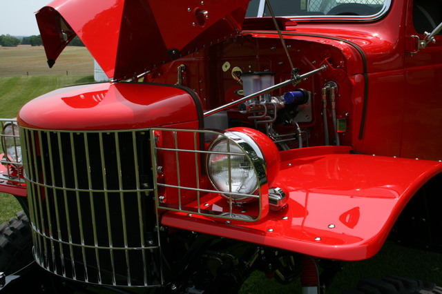
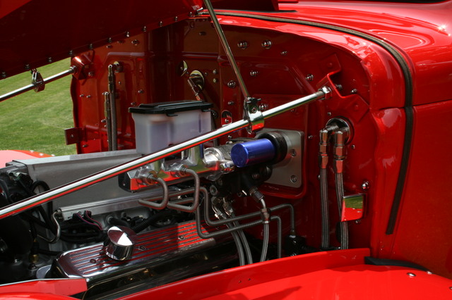
I had to shim the cab higher than during my mockup phase for some reason as it was contacting the transmission. This meant that the radiator cowl also would have to be raised to make the hood fit correctly. It also means the clearances I had before are all different. I built some spacer plates to go between the radiator cowl and the frame, but that changes fit of the radiator hoses, fans, and connections. I had to build a new mounting plate with longer bolts as well. It also was needed to try and keep the clearance between the brake booster and the hood. I originally angled the booster assembly up to clear the motor, raising the cab means I didn't need as much angle, and also removed the minor clearance I was going to have to the hood. I used a straight edge first to get an idea and still had issues. So I found a different, shorter master cylinder tank to try and add some space, and then tried test fitting the hood.
The end result wasn't good. Two issues became apparent. First I was close but still hitting the hood. I could close it but it was pressing into the hood. Second the prop rods for each side want to rest right where my cruise control box is mounted.
For the clearance issues I basically decided to add some stainless washers between the top of the booster mount to flatten the angle down since I had plenty of extra clearance to the motor now. Afterward I ended up thinking that I had probably not shimmed the cab to the same level I had before, and it was slanted slightly rearward, which would explain what's been causing part of the clearance problems. I may add some shimms to the rear, but that will again cause other problems, so for now we'll try the booster shims.
Still not sure what to do about the hood props, but at least the hood gaps seem to be pretty even, if maybe a little large, that's a plus.Leave a comment:
-
Thanks to AlxJ, I backpurged the piping and welded up the seams in the exhaust piping. I would weld a section of each joint, then rotate the pipe to get at another section and repeat. It helped let each joint cool between welds, though some of my less-tight gaps had to be sealed with tape to prevent the gas from leaking out. The end result might not be anything a welder would want to lay claim to, but for me some of it is almost good, and should be strong enough for what I want. I also finished welding and cleaning up the mounting brackets to the piping as well. Afterward all the seams got hit with a wire brush to clean them up a little and get rid of any discoloration.
Somehow it all seemed to fit right before I took it apart to weld. While it went back together well enough the rear two mounts were somehow further back then before. The rubber mounts accounted for the movement but it's always frustrating when it comes off one way and doesn't go back together the same way.
Still not sure if I'm just going to leave the downturn or weld in a longer pipe exiting in front of the rear tire. Plus side is being after the muffler I can easily change it later once I have the running boards and correct tires in place and build it then.Leave a comment:
-
Ha! It's a double edged sword. I wanted to make sure there was the detail that others crazy (stupid?) enough to follow would find helpful on both what (not) to do, but also make sure people knew what they were getting themselves into. The climb to the top never looks as long as it is, I started this figuring it would be 3 or 4 years. I think I'm looking at 6 or 7 now and still not as close as I think I am.Originally posted by PaulD View Post
I'm excited, but trying to keep my expectations realistic. This isn't going to be "done", I'm sure there will be stuff that isn't going to work as well as it needs to or should. Just hoping that the major stuff is right. Actually need to post up some of my recent mistakes, just haven't had the time.
Well, for better or worse it will be a learning experience and that can never be a bad thing. Just return the favor and start a thread and let us all know what you're doing. Include plenty of pics because we all like to see what's going on. Good luck and welcome to the madness!Leave a comment:
-
Font end clunk
Appreciate your idea of what might be causing my front end clunk. I'm busying for the next few days but will look into it soon. I'll try for picturesLeave a comment:
-
Thanks a lot!!
Hey Desoto61, first of all thanks for wasting almost an entire day. I found this thread and had to read every post because I got hooked on the build. You really have provided a great resource of information. Second, because reading great build threads like this is inspiring I pulled the trigger on a 56 PW I'd found a couple miles from my house. Always wanted to buy it but resisted until now. Now my wife is mad and I have a ton of work (fun) ahead.
Seriously, thanks for the great detail you've included to help others following with their builds. Yours is looking fantastic!Leave a comment:
-
Sorry to jack the thread a bit. Hey cartridge I had a front driveshaft clunk as well, it was the rubber trans mounts were loose from time, caused the shaft to rub and clunk. Might be your issue. Just tightened them up and problem solved.Leave a comment:
Leave a comment: