added a bit of Alex to my shroud
The truck seldom runs hot. The only time it ran hot was under load. Either at slow speeds in the bush or climbing a real long steep grade on a highway. The truck is running a 16" puller fan. The rad is a recore stocker, so basically new and the water passages in the block are pristine. There are several steps I am going to take. the first will be to build a shroud and if that does not help then a second pusher fan and hood louvers get added. The shroud should do the trick.
Check out the mounting tabs on the shroud. Took a silly amount of time to mount these in place. All told 68 holes were drilled and lots of trial tests to fit the shroud. So I have the look of rivets but they are not rivets, they are doctored button head screws.
-
Are you running hot quite frequently? And are you using a pusher and or puller type fan? Cooling these trucks is a common problem. I truly love your designs and craftsmanship. Thank you again for sharing with all of us.Leave a comment:
-
I will have to add this to my (long) list of future modifications! I had to sneak in two smaller fans to get them to fit, I should be able to install one larger, more effective fan this way!
Thanks Bruce!Leave a comment:
-
Shorten your Cummins by two inches.
I have an issue with my cummins block overheating. This only happens when driving under load and the speed is slow, like under 5 miles an hour. Due to area restraints it is next to impossible to run a mechanical fan on the front of a Cummins block in the confines of a WC or PW truck. Most of us use an electric fan. Some place pusher style fans in front of the radiator but I like the fan at the back. To get the electric fan in place it was necessary to attach it close to the radiator. The fan was mounted about 3/8 of an inch away. Even with it that close to the radiator the bolts on the Cummins fan pulley contacted the electric fan on occasion. There was no room for a shroud.
The solution to getting enough room for a shroud and mount the electric fan away from the radiator was to build a new mount to replace the old mechanical unit.
The solution was quite simple.
(1) I traced the old fan mount base on to a block of one inch thick aluminum
(2) I purchased a late 2000 Cummins idler pulley, comes with a bearing and bolt
(3) I marked the pulley centre of the old mount on to the block of aluminum as well as the outside radius of the old pulley
(4) the new pulley is smaller, it needs to be moved out 45 degrees from the old centre until it is about 1/4" away from the old radius, at this point a new centre hole for the pulley can be marked and tapped.
(5) to set the correct depth for the pulley you set the new unit and the old side by side on a flat surface. The new pulley has a mount on it that needs to be machined down.
The nice thing about this is if there is a bearing failure the replacement pulley will be a stock Cummins part. By going this route I now have room for a shroud. The fan is not mounted at this time because I am waiting for a lower radiator hose elbow. As usual each part takes two weeks to get here.
edit: the piece of beige steel with 18 1/4" in felt pen written on it is the top of the new shroud.Leave a comment:
-
test post
I seem to be able to post pictures, not sure when that happened, so get ready for more eye candy.
I ran across a transferase rebuild kit for a WC53. seals and gaskets for 500 bucks american? I think an hour or two with a micrometer and you could order new bearings and seals for a lot less than that. gasket paper is not that difficult to cut.
This is the $56,000 dollar truck.Leave a comment:
-
another WC53 on ebay
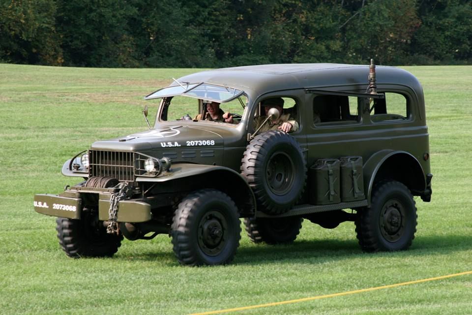
This one is fully restored but is being sold by another party. We have seen this one before. The truck has the spare tire mount, 2 jerry cans on the drivers side running board and a mess of radio equipment and a tool pouch.
$56,000 bucks? We shall see my impression is the prices on these trucks has peaked.
My truck? I am waiting for that silicone boost tube to turn up, at which point it will become a coolant hose.
I did rebuild two transfer cases over the last week, I am creating a doubler for another vehicle. The NP205 is now a hybrid of this and that.
Bruce
__________________________
wrench bender and busted vehicle ownerLeave a comment:
-
Hey Alex, thanks for all the details. Please post a link here when you get the other thread started. Your work is much appreciated.Leave a comment:
-
Just saw that there is going to be a Legacy Carryall on Jay Leno's garage here soon. They are headed off to film it in the next few days.Leave a comment:
-
I'll answer below using your original format.Originally posted by Greg Coffin View Post
- What did you end up using for you rivet sets?
I machined and heat treated some SAE 8620 using an 11/16" diameter Carbide end mill held in my lathe. For the bigger hammer, it uses the oval type retainers for chisel work, vs the original type spring clips; I tried to cheat (all the time knowing better) and cut the shank off of some tool steel bits that I have. I then heated them in the forge with the 8620, and then let them both cool at the same speed to normalize them. I then welded them together using some RN60 Ni-Monel filler rod and then just heated the end of the setter and water quenched that (per the ASTM guide on the material) and used that. Well, my normalizing attempts didn't work for the tool steel and I still ended up with cracks. It would occur when the hammer die would get "snapped" from a skip off of a rivet. Ie, the tension energy wave was harming the setter, not the compression loads. I made two this way, one long and one short. They both cracked and one failed before the hammer operator could get off of the trigger. However, they did set about 30 rivets each before the failures occured. There are 96 total in this assembly. I had to resort to my other smaller hammer that used the safety wire retained setting die that was all machined from one piece. There are some pointers involving making the dies too but thats for the other thread, as is most of this info.
- Did you have someone backing the rivets for you?
I'll add a picture of my anvil setup. I took a piece of 3/4" x 4" A36 flat and drilled three (3) holes at 1" dia each. I then used some chain, close anchors, and turnbuckles to hold the flat bar transverse to the top of the anvil. In the center hole I placed a solid machined and heat treated / quenched piece of 1" diameter round 8620. It stayed in place very well; only had to tighten the turnbuckles like one time after all the vibration got things centered. I had two buddies help hold the parts level and it was totally a 3 man crew job.
- Are the heat signatures from heating the rivets in place, or conduction from red hot rivets heated in a forge?
Both actually. The forge and direct driven rivets still created a heat signature of about 2x the diameter of the rivet heat. However, the torch did get used later on in the process when we realized how much of a heat vampire the parts were during assembly. The material is only 1/8" thick so it doesn't take much to heat soak either. See next question for further explanation..
- Are they 3/8" rivets?
Yes, 3/8" from Jay Cee Rivets, mild steel, 1" long shanks. That was the correct calculated length to get the material for the grip and then enough to form the tail dome. So basically, grip length plus .75" if you are running 3/8" rivets. And if it gets too much deeper of a grip, maybe add another 1/8" because you start to lose volume in the reamed holes. That being said, about the above heat issue... 3/8" rivets shed heat VERY fast. Not much volume to surface area ratio so the plates would suck the hot right out of those little things, especially when you think how much the volume of something increases with just a minor increase in diameter ((L*Pi*R^2) vs (L*Pi*R)) so bigger 5/8" and up rivets retain their white glow a bit longer and stay workable due to a better volume to surface area ratio. That being the case, we learned to heat the plates with the torch around the hole before snagging the rivet to get it in set, especially if it was somewhere hard to get to. Also, in the corners, we'd set the rivet, and because of my poor offset planning, we'd throw the torch back on and bend the shank over a little bit with a spud wrench and then set it with the hammer. Heating in place is less than ideal for structural application because it softens the main plates so when the rivet cools, so does the fastened plates at the same rate and effectively the rivet is kinda loose and lacks that "tightened" application.
Yea, this is complicated... and did I mention the "feel" that you have to get for the hammer and such too? Ohh, and just having an overall process and all operators on board paying attention, air supply ready, etc... Sheesh! It was an adventure, but it was very fun and I WILL be doing it again. I just have to machine my full die sets and not be lazy and try to weld them to chisel shanks...
That part on the anvil is just my ugly little test piece.Leave a comment:
-
Nice work as always Alex. I have a couple (dozen) questions:
- What did you end up using for you rivet sets?
- Did you have someone backing the rivets for you?
- Are the heat signatures from heating the rivets in place, or conduction from red hot rivets heated in a forge?
- Are they 3/8" rivets?
Very nice work.Leave a comment:
-
Finally got around to it, been dealing with some "life stuff" that has kept me down and out. Despite my best efforts, my attempts to weld 8620 to Tool Steel did exactly what I expected it to do... cracked. But not a problem as I had made some complete die sets too.Originally posted by Matthew Welcher PWA View Post
Greg, thanks for the looking out! I needed to ditch that quick fitting anyways due to it being so small and restrictive so I went ahead and installed a short whip-line like you suggested. Worked out really well. I ordered some crimp ferules and used my AC hose crimper to make some nice clean hoses. Since the old spec sheet I found for the hammers say that it needed a 1/2" hose, I upgraded the outlet on my tank and have a direct drop line from the tank to the gun so that I am not losing energy through my intricate 3/8" shop system. It certainly made a massive difference in the amount of energy that both hammers could deliver.Originally posted by Greg Coffin View Post
Goose, welcome to the forum! Sounds like an interesting project. Just make sure you take your time and don't cut corners when mixing the old with the new. Post some pictures to show what you've got going on so far. Thanks for the compliments on my project, its honestly a mess but I have an end product in mind each time I start a new piece of the truck. Getting there, slowly, but very surely. In regards to the CAD stuff, I lost most of those files in a hard-drive crash not long after completing that portion of the rebuild. The other thing is, my dimensions are based on where I could stretch my truck back to and FWIR, they didn't exactly match the dimensions I took off of an original straight body truck located about an hour from me (no, he won't sell it guys) so I used those as a baseline and then constructed mine to be a "build to suit" kinda thing. I actually have been lately displeased with it all and may have to cut into things to clean up some stuff before I get this truck painted.Originally posted by Goose View Post
So, a few pictures of my skid, since this forum will only let me upload 3 at a time. I won't instigate boredom with the details here but have plans to (Matt, keep poking me if I don't) establish a thread in the tech section about the hot riveting experience.
I still have to make and attach the support brackets and the tank hold down strap terminations, but you guys might get the idea? They aren't all perfect, but that might be a good thing to convey an "original-ish" appearance rather than looking like they were never touched with a hammer and welded from the backside or something. Because of the heat signatures on the plate parts, I was already accused of welding them and not driving them on another board so I posted a video on Instagram of the hammer running. They then deleted their accusation.Leave a comment:
-
Aliens in Carryalls
IF I can get the load of stuff I picked up from the sand blasters today, painted.. I hope to get some of the front of the truck put back together. There's still some show stoppers though. I've a shipment from Midwest coming in, hopefully early next week? It has some bits I need. Like the silly plate & screws for holding the hood to he nose of the truck.
Now here's a thing..
Look closely at the passenger. You tell me that doesn't look like a human sized cat riding in there. Whiskers and all.
-jim leeLeave a comment:
-
Good to have you on board Goose.
Looks like this blown head gasket will come out to about 2 grand in parts. Good thing we do our own work, I think it would be closer to 8 grand if I had the work done at an outside shop. I turned down the injector tips from 9mm to 7mm. Problem I then had was which washers to use, 7mm injectors seem to use thicker washers than 9mm injectors. I have no idea if the bore depth seat are changed in the head from one block to the other - but I gambled and used the thinner 9mm washers. I managed to check the spray pattern on the injectors but did not do a pop test, that I will do at a later date.
I have a shroud half made, it fits better than I would have expected for a first try. I want to move the bottom hose away from the radiator a little bit. To do so I need a hose with a tighter radius. Silicon turbo connectors can be had with a tight radius. I dropped by my local shop - $70 bucks, so I ordered one on epay instead - $20 bucks to my door. this will set back my first test firing of the truck by about 12 days but I felt the cost was silly for me to buy locally.
Genos! So I bought a banjo bolt from Genos, this is so I can run a line and a sender to check my fuel pressure after the lift pump. The bolt was a hair too big. The Cummins bolt mics in at a shade under 12mm and Genos bolt a shade over 12mm. I tossed it in my lathe and was going to try turning it but elected to hit it with a file instead. Three or four strokes and it fit just fine. When I attempt to fire this engine up I will purge the lines in the hopes that I can clear any degree left in a line.
Way fun
Bruce
Speaking of way fun, Jim you have your engine compartment torn apart. We could use some pictures. Too bad I am too many ferries away. I would weld em up for you.Leave a comment:
Leave a comment: